Overview
This page will give you an overview over the different Components that you will start to understand along the process. Those are the building blocks of the project, understanding each of those is key to build something like the Grinduino!
Components
USB-C Trigger Board
The USB-C Trigger board is responsible for providing the system with power. It has switches that you can flip to adjust the Voltage that it will put out. This only works with a PD USB-C plug.
Motor Driver
The motor driver acts like an interface for the motor, it can tell the motor, how fast it should spin and the direction. It has some safety mechanism as well to protect the other parts from Voltage fluctuation that the Motor causes. The Driver is directly connected to the 20V Power source and it also has a Output terminal that has a output Voltage of 5V, this is excellent to power the Microcontroller and to protect it from the higher voltage.
Microcontroller
This is the brain of the application. It processes signals from the other components and sends out signals to for example start the Motor or Print something on the LCD Display. The Microcontroller, gets its power from the Motor Driver and then Distributes it to the other smaller components of the system.
Potentiometer
The project has 2 potentiometers, those are little knobs that you can spin and adjust resistance. You can read those values with the Microcontroller and therefore use the potentiometers as input values. In our system we use the potentiometers to set the RPM and the Grind Dose.
Button
In our system we have a pressable button which is being read by the Microcontroller, if the button is pressed and the Motor is off, the motor starts, if you press the button and the Motor is on, the motor stops.
LCD Display
The LCD display works as an interface so the users can see the values that they are changing when spinning the potentiometer. What is being printed on the LCD decides the microcontroller.
Scale
The scale in our system is being read by the Microcontroller during the Grind. It detects the ground coffee that falls into the Dosing Cup. The Microcontroller sends a stop signal to the Motor as soon as the Dose input value from the Potentiometer matches the output value from the Scale.
Switch
There is also a Switch that can turn off the whole system if its not being used and the user doesn't want to have the LCD light on.
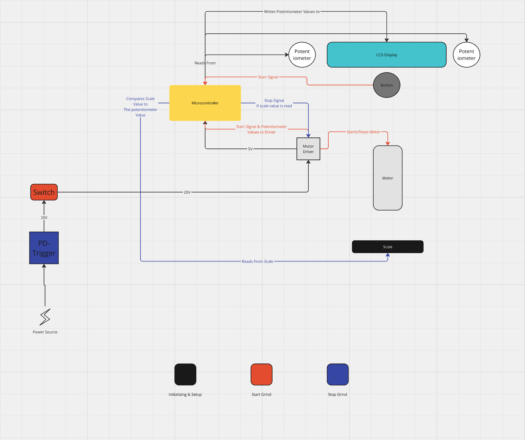
Component Diagram